Speaker III – Crossover Design #2

img008

The next crossover design. The target for this crossover is a 4th order LR at 2.5 kHz. The tweeter circuit is electrically 2nd order at 3.6 kHz which combines with the natural 2nd order low-frequency roll-off of the tweeter at 1.0 kHz. Two tweeter circuits are shown… the top is a basic 2nd order with attenuator. The bottom circuit also includes a phase shift circuit. The mid-range circuit is truly 4th order electrical, although it is not a electrically LR.

Here is the crossover prototype boards. Sub-circuits are on separate boards so inductors can be separated in the cabinet – tweeter crossover, tweeter delay and attenuation, and midrange crossover.  The alligator clip jumper wires will be explained below…
2014-01-18 17.56.34

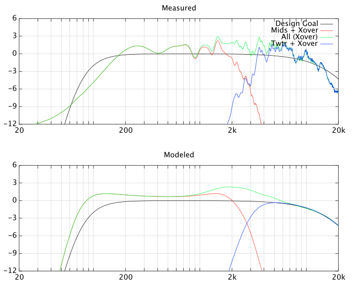
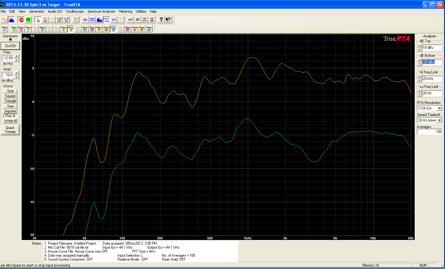
Testing determined two necessary adjustments. First, the tweeter was “hot” by about +2 dB.  The attenuator resistors were immediately adjusted from -3.5 dB to -5.5 dB of tweeter attenuation.  Second, a suck-out at 3-4 kHz can be seen in the response graph below (lower trace).  The suck-out was verified to NOT be a polarity issue.  An appropriate deep dip was observed at 2.5 kHz when the tweeter polarity was reversed.

The dip was mitigated by increasing the tweeter output in the 3 kHz region by lowering the crossover frequency and increasing the filter Q.  Adding a 4.7 uF in series (via the jumper wires shown above) for a total of 13.7 uF did the trick (upper curve).  Note the curves are measured under identical test conditions – a 10 dB offset is added for ease of visualization.

2013.12.30 4.7 uF

These results emphasize the importance of having some type of acoustic measurement capability when designing loudspeakers!

Speaker III – Prototype #4, The Return

It has been a long time since I have worked on a speaker project.  I have lots of parts sitting in boxes, just longing to become a full, functional speaker!  So this holiday season I decided to get back onto the horse and finish up Speaker III.  The first step is to figure out where I left off.

The first problem is the shielded tweeter.  I only bought two, and they are not available anymore.  This is not a bad problem – LCDs are the norm today and magnetic shielding isn’t as desirable as when I started Speaker III in 1998.  I found a substitution in the way of the Vifa D27TG-05-06.  It is a silk dome with ferrofluid like the D27SG-05-06.  Efficiency is similar between both units at 91/92 dB/2.83v, as is the resonance frequency of 1,000 Hz.

It is a lot of work to make your own cabinet with the number of small internal pieces.  So I decided to use a pre-fabricated MTM (mid-range / tweeter / mid-range) cabinet from Dayton Audio.  Internal volume is 0.75 cubic feet. The front baffle is removable and ready for your driver cut-outs.  Here is the Front Drawing with tweeter and mid-range locations and cut-outs.  Note how the lower mid-range is further away from the tweeter than in Prototype #3 (I will show why this is not good later in testing).

Well, I didn’t save myself that much work.  I wanted to do a round-over on the mid-range cut-outs based on my research into cleaning up the tweeter response.  I couldn’t find a router bit that would let me do that – not at a price < $100 anyways.  The solution was to make my own baffles out of two pieces of half-inch particle board and glue them together after making all the routes and holes.

Baffles drying after application of epoxy

Baffles drying after application of epoxy

Where did the work come in?  Trying to finish the baffles as nicely as the factory baffles.  To achieve a smooth finish I coated the baffles with an epoxy product.  Which I then sanded.  And then applied another coat.  And sanded.  And again.  And again.  Then I finally sprayed on a black laquer.

Baffle Black 1

Baffle Black 2

Speaker III – Crossover Design #1

The design of the first cross-over is done. The target is an acoustic 4th order Linkwitz-Riley at 2500 Hz. My simulated target responses using measurement data taken using a ground plane at 72″ is on the top (the data is not measured with crossover network, it is measured then a crossover simulated).  The bottom plot is based on a simulation of the drivers + crossover (which is why it is so smooth).

Screen shot 2014-01-18 at 11.17.16 PM

The electrical network is shown below.  Electrically the tweeter slope is 2nd order, and the mid-range unit crossover 3rd order transitioning to 2nd order (that is what the 1.5 ohm resistor does connected in series with the 18 uF cap).  Zobels are used on the mid-ranges.  Zobels are even on the mid-ranges before and after the 1/2-way cross-over inductor.  (Note shown: the capacitor value is 45 uF in series with 7 ohms for the Zobel to the left of the 1.8 mH inductor.)  The Vifa D27SG-05-06 has a faster high frequency roll-off than similar tweeters.  To compensate, the attenuation resistor is by-passed with a 15 uF capacitor.

img007

My First Home Theatre Setup

LivingRoom

The main loudspeakers are Speaker I, and the surrounds (not visible) are my own dipoles. No center channel at this time, nor side speakers.  The love seat is for the theatre, the main couch is for the Apogee Scintilla setup on the opposite wall.  The bass was quite good in the corner like this, and the imaging benefitted from only one reflection from the right wall.

HomeRack

Just a quick snapshot of my rack. Amplifiers are Parasound 750A for the surrounds, Adcom 5500 for the bass modules, and an Aragon 4004 mkII for the satellites. The surround processor is a Lexicon CP-3 with “+” software. The electronic x-over is a Marchand XM-9. The crossover frequency is 250 Hz. The source is a Pioneer DVL-909 which is a combination compact disc, laser disc, and DVD player.

Apogee Scintilla

ScintillaFront

This is an Apogee Scintilla, probably made in 1986 or 1987. (Texas size, 18 pound cat named “Chester” added for scale.) The diaphrams are Kapton film with aluminum foil conductors. The tweeters (4 of them, 2 front, 2 rear) and mid-range are suspended between a 2″ wide by 1.5″ deep by 54″ tall magnet gap composed of 2 double rows of magnets. The woofer ribbon diaphram is in front of a perforrated sheet of steel onto which are attached rows of magnets. The magnets alternate polarity so as to provided the same direction of force to the aluminum trace which “snakes” down the Kapton film. All of those magnets make the system very heavy: 140 pounds per speaker!

The system powering them in Oct ’00:

  • (Top-Left) This amp-sized item is not an amplifier, but a Theta Digital Data II combination Laser Disc / CD transport (1995 vintage).
  • (Bottom-Left) A Theta ProProgeny A DAC to match the transport. Actually, it a bit newer than the transport (1999 vintage). I selected this DAC based on reputation, but also because the output voltage is better than 4 volts for full swing.
  • (Bottom-Right) The pre-amp, a McCormack TLC-1 was rated stereophile class A for its pair of unity gain outputs: one passive, and one buffered. No pre-amp gain meant selecting a DAC with higher than normal output voltage.
  • (Top-Right) Amplification is via an Adcom 5500 that used to be on subwoofer duty in the home theatre. The Adcom does have some turn-on thump that I don’t like, but IMHO it is the most heavy duty of the regular offerings (the 5802 and HCA-2200 don’t count as regular) of Parasound, Adcom, and Rotel. I had originally tried to get a Parasound HCA-2200 II (it is rated to run bridged into 4 ohms, very rare), but the deal fell through.

However, as pictured above, the sound wasn’t the best. The sound was very laid back. The Scintillas sounded as if the upper vocal registers and the mid-range up to 1-2 kHz were supressed. Since I was not the only one that has heard this sound characteristic, I did not think anything was terribly wrong. Not so! The correct placement is to put the mid-range / tweeter ribbons on the inside:

ScintillaGood

After getting the setup right, I was an order of magnitude happier with the Scintilla sound. The ribbons are truly the jems of the speaker and it will take some serious comparison testing to the Martin Logan CLSIIz to decide if any one is better. The sound is stunningly detailed and smooth in the operating range of the mid-range and tweeter with no hint of a cross-over transition. Imaging is very good; before flip-flopping there was sound stage in the center, and to the extreme left/right, but no where else.

I’m still experimenting with the Scintilla’s position which greatly affects how strong the bass output is. Originally I had them 2′ from the wall which produced overpowering bass in the 30-40 Hz region. Since them I have moved them out to 4.5′ from the walls, but the amount of 30-40 Hz bass is still slightly unnatural. Getting the mid-range / tweeters in the right position helped the bass balance even more. The strategy appears to be to position the speakers in one of the listening room’s bass nulls to cancel some of the bass. The result, done properly, should be amazingly flat bass response throughout a whole room. I have yet to play any music loud enough to make the bass panels move except for a Telarc disc where a T-rex eats you for a snack. No subwoofer I have heard has been this good. After all, the bass radiating area is the same as eight 12″ woofers (or just a litte more than five 15″ woofers, or a little less than four 18″ woofers)!

Something to keep in mind is that these speakers are 13-14 years old (at time of my purchase). Inductors have come a long way since then, and capacitors even more so. Plus, my experience is capacitors do degrade over time (especially electrolitics), and the Scintilla’s capacitors would be large and have been getting a good workout over the years. Some replacement of these parts is probably in order. More important is tensioning of the bass membrane. There is some breakup buzzing in the 200-300 Hz range which is audible on male voices and with 1/3 octave pink noise tests.

I also need to try some more powerful amplifiers. The 5500 clips on deep bass notes when the sound is moderate (sorry, my Radio Shack SPL meter is broken). It just doesn’t have the output transistor count for driving so much current all of the time. Below is the impedance curve – 1 ohm in the bass, with a rise to almost 2 ohms at the cross-over between the bass panels and mid-range.  The 5500 never shut down mind you – I just didn’t perceive the bass quality I was expecting.

Impedance


AES Speaker

AES150
This very unusual speaker was built by Tim, Ryan, and others as a show project for the Michigan Technological University’s Student Audio Engineering Society chapter. The year was 1997. The drivers were one of the Raven R1 tweeters, 7″ Focal hi-efficiency mid-ranges, and 12″ Focal woofers. The general construction was dipolar to save weight. Two of the mid-ranges have cloth covered foam pieces over them to control dispersion (those are the black things). The woofers are wired in parallel to counter the dipole loss in bass efficiency, but that made the impedance around 1 ohm. The baffle is a light weight balsa composite, and the yellow stuff is a spongy, “memory” foam.

Magnetic Lines of Force

Magnet150
This is an older 15″ EV driver mounted “backwards” in a test cabinet (actually Speaker II). While disassembling the test setup I placed the screws on the speaker without even thinking about what would happen. The magnet on this driver was so strong that it lifted up the screws along the magnet lines of force.

Test Measurements

This is the test setup in my living room. (The microphone is close in this photo because I just had finished some “close mic” testing.)

I mounted one ribbon unit on a 2’x4′ sheet of 3/4″ thick MDF. The slot in the front is 1/2″ deep and has a 45 degree bevle. You can see wholes in the baffle where I had to drill holes to allow some screws to poke through.


The pic above illustrates the cross-section of the test baffle showing how I routed a recess for the driver to mount from the rear (one square = 1/8″ on a side). The lip on the inside was suppose to compress the foam, but without screws in the middle of the frame, the frame was bending from the pressure. So I had to loosen the assembly, leaving about a 1/4″ foam sealed gap between driver and baffle.


This is the response measured by my Liberty Audio Suite setup. In this case, the microphone is about 20″ away, and the time window of the measurement is long, 75.8 milliseconds. The long time window allows quite a bit of noise into the measurement, so this plot is smoothed with 1/3-octave filtering.

The reason for using the long window is to obtain low-frequency information. Unfortunately, the noise level is too high in my apartment. Everything below 200 Hz is bogus.

The response in the mid-range and high frequencies is valid. You can see that the response doesn’t go much beyond 10 kHz. There are dips at about 1.5 Khz, 3.5 kHz, and 7.5 kHz. The dips are pretty narrow except at 1.5 kHz, so probably aren’t that audiable (they are comparable to that from placing a frame-mounted grill over a conventional speaker). A frequency of 1.5 kHz is a wavelength of 23 cm / 9 inches. That would be the distance between the aluminum support bars. It is also about the distance from the left baffle edge to the driver opening. Hmmmm… more testing is going to be required.


These two response curves are measured with the microphone only 1/4″ from the membrane. For the first, the time window is 17.9 ms, the second 77.7 ms. They match the trends in the far microphone measured response in the mid-range.

Noticable is the hump in the response at about 300 Hz. Looking at the time response directly, the resonance at 300 Hz is clearly visible and real. It lasts for about 3 half-cycles, then dies down down significantly. I believe the hump is there on purpose; if this test was done on a narrow baffle like the designers intend, the curve would smooth out. Why… on any baffle the sound from the back of the driver cancels with that from the front in the low frequencies. The narrower the baffle, the higher the frequency at which the cancelation occures.

Roughly, cancelation starts at 200 divided by the width of the baffle (result in hertz, units of width are meters). Given the rise in response starting at 1000 Hz, my guess is the “recommended” baffle width for these was 8″ (20 cm).

Martin Logan CLS IIz

MeCLSII

This is what a CLS IIz looks like with the black finish. (5’10” author added for scale.) The diaphragms are transparent which is not easily discerned due to the camera flash. For much more information you should visit their site.

TheTable

The system powering them in Nov ’99. The large, amp-sized item on the top left is not an amplifier. It is a Theta Digital Data II combination Laser Disc / CD transport. To the right is a Rotel RDD-980 transport which I originally bought for my CLS II system. The DAC is a Theta ProProgeny A (left 1st shelf). This DAC impressed me so immensely with its construction quality that I decided to replace the Rotel transport with a Theta transport. The pre-amp is a McCormack TLC-1 (right 1st shelf), and amplification is a pair of ’91 vintage PS Audio Delta 250 monoblock amplifiers (left and right bottom shelf). Later I upgraded to an Aragon 4004 (below).

TheTable042800

This purchase was not initially stress free.  The frame split on one of the two panels during shipping.  I ended up repairing it myself.

DamageFront1 DamageFront2

You may have heard that the impedance of electrostatic speakers is very low at high frequencies.  I took some measurements of the undamaged speaker, with and without the power applied.  That’s under 2 ohms at 20 kHz !!!

impedance_both