In this installment of Unbaffled, I test three different dipole low-frequency configurations.
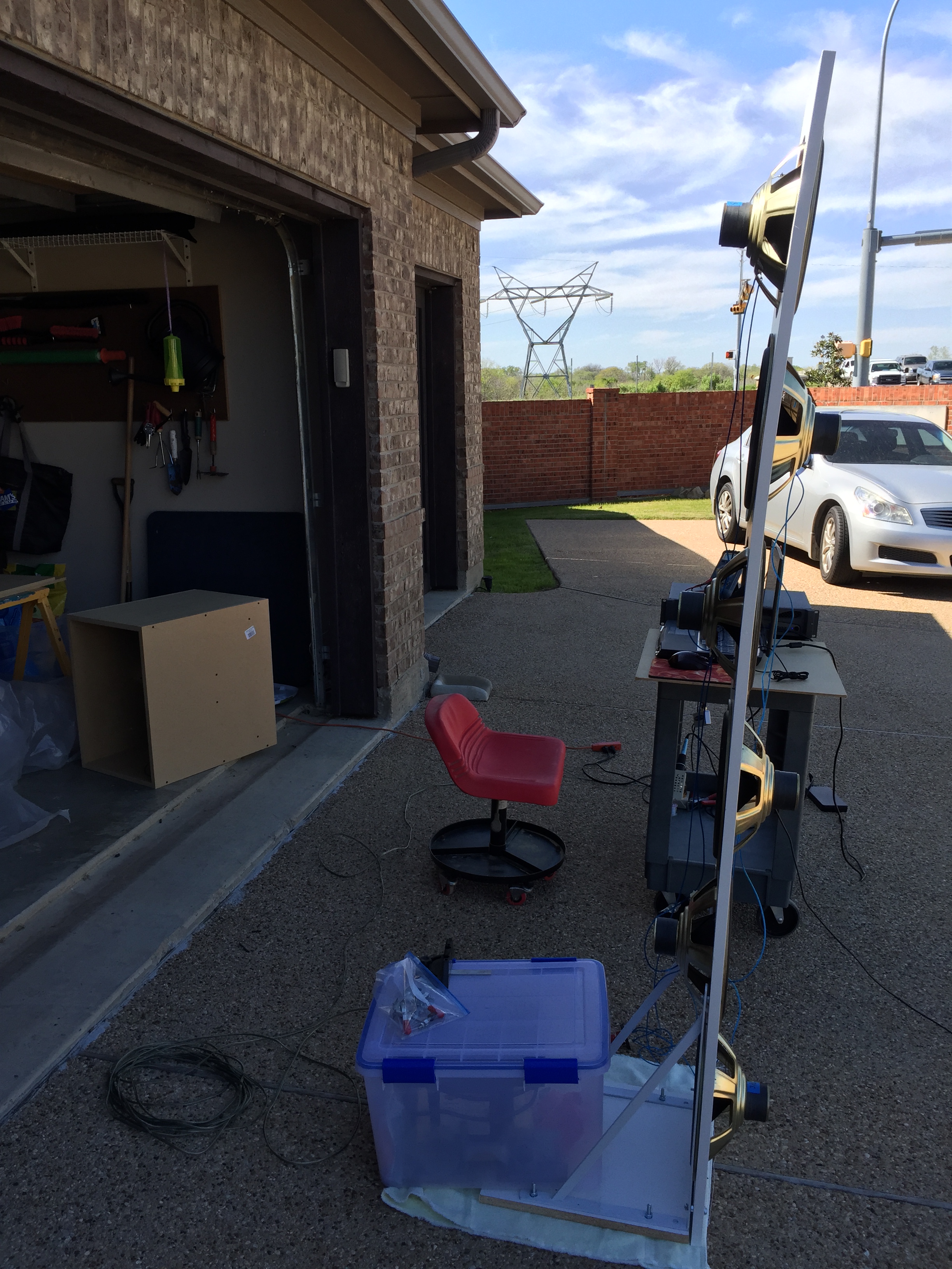
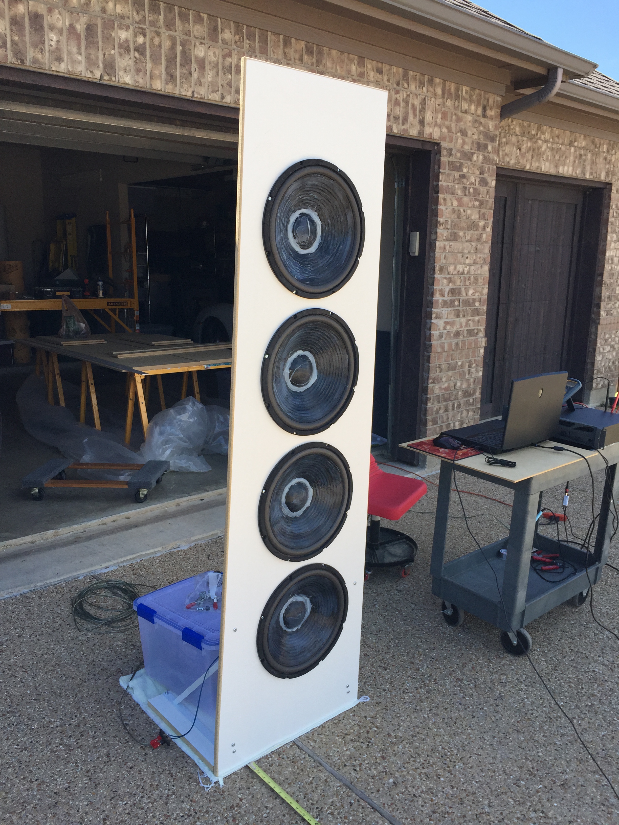
Up first is a 4 x 15″ driver configuration. The woofers are value priced models from Goldwood. You can see something on the cones – that is silicon that I added to them in order to lower the resonance frequency from 30 Hz down to 24 Hz. (As a side note, I would recommend using a black silicon instead of clear. The clear silicon doesn’t have a very attractive appearance.)
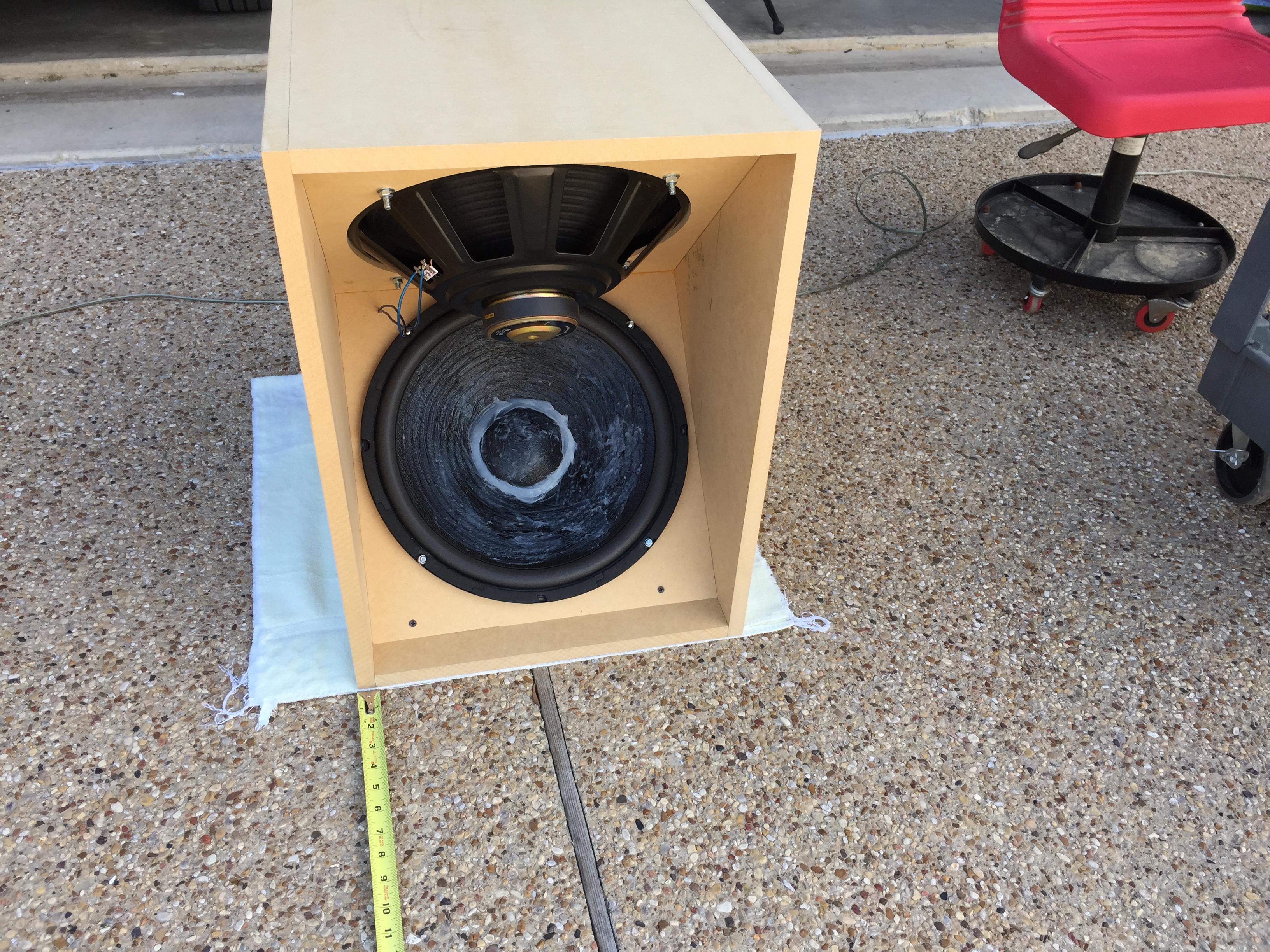
I also built an H-dipole recommended by Linkwitz. This was really easy to build, OK to move, and much stiffer than the 81″ tall panel version above.
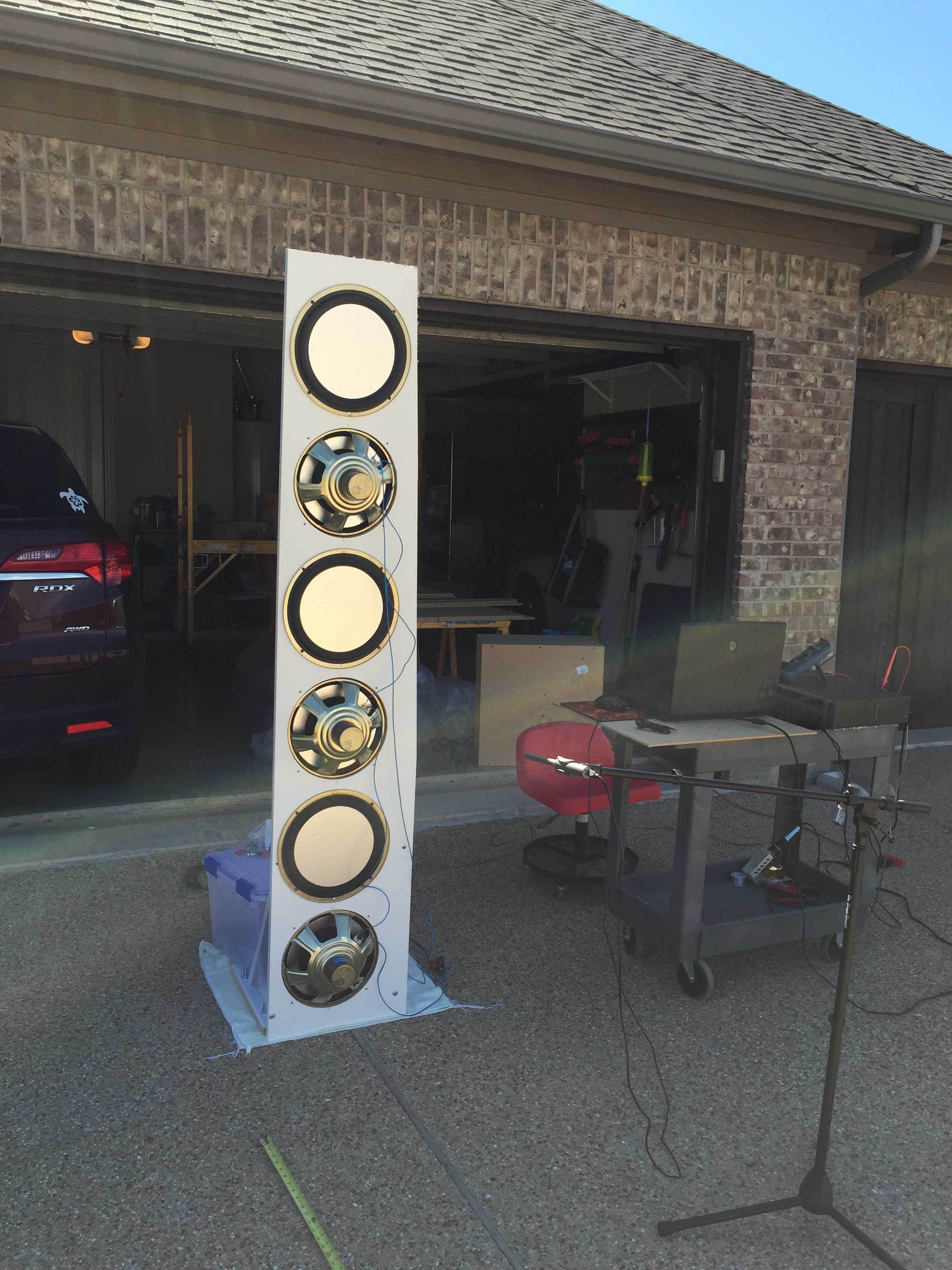
Finally, six of the 12″ carver hex woofers from the original Carver Amazing loudspeaker. Notice that half of the drivers are reversed – and connected electrically out-of-phase – so that some of the even order non-linearities would cancel out. The drivers are connected 3 in series / 2 groups in parallel. The panel is about 15″ wide at the bottom as I was not able to find the 24″ wide board that I used to make the 4 x 15″ dipoles.
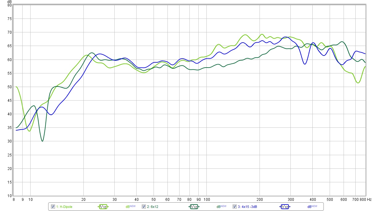
Here are some measurements adjusted to be equal in output. All measurements are smoothed by 1/24th octave filtering to help reduce the noise from the wind.
- Green = H-dipole response measured with the ground plane method at 2 meters.
- Blue = the 4×15″ dipole panel with the microphone at 1 meter, 41″ off the ground (which is the center of the 4 drivers). The level is reduced by -3 dB relative to the H-dipole.
- Red = the 6×12″ dipole panel with the microphone at 1 meter, 41″ off the ground.
I was surprised at how close the H-dipole configuration behaved compared to the panel. I was expecting the H-dipole to show more peaks and dips and otherwise be a poorer performer. Not so! In fact, I like the fact that the H-dipole forms a naturally well braced cabinet. The two panel designs both bend like a reed in the wind and flop around at low frequencies (4 Hz is especially violent).
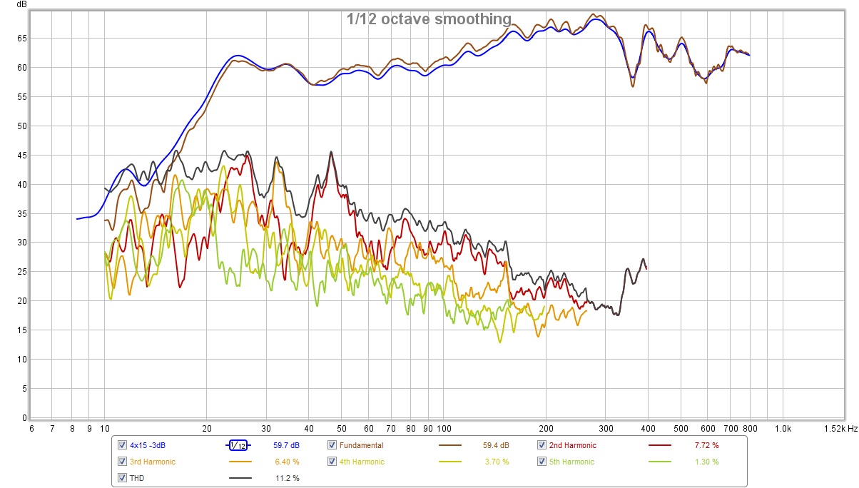
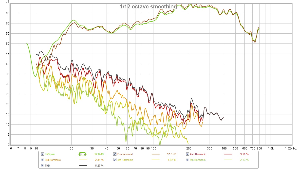
 Next up are some distortion plots. An important caveat is in order here – the wind and automotive traffic were rather problematic during testing. The plots are in the same order as introduced above. The H-dipole plot was the least windy and shows the best results.
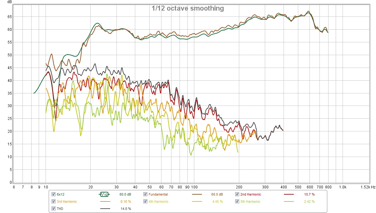 Another note is in order… the 6 x 12″ dipole panel was damaged because it fell over and cracked. Moreover, I had to swap out two of the drivers as they now buzzed. (I had just enough spares.) You can see that the panel isn’t quite straight at the top. The whole thing fell apart when I finally removed the drivers for the next prototype.