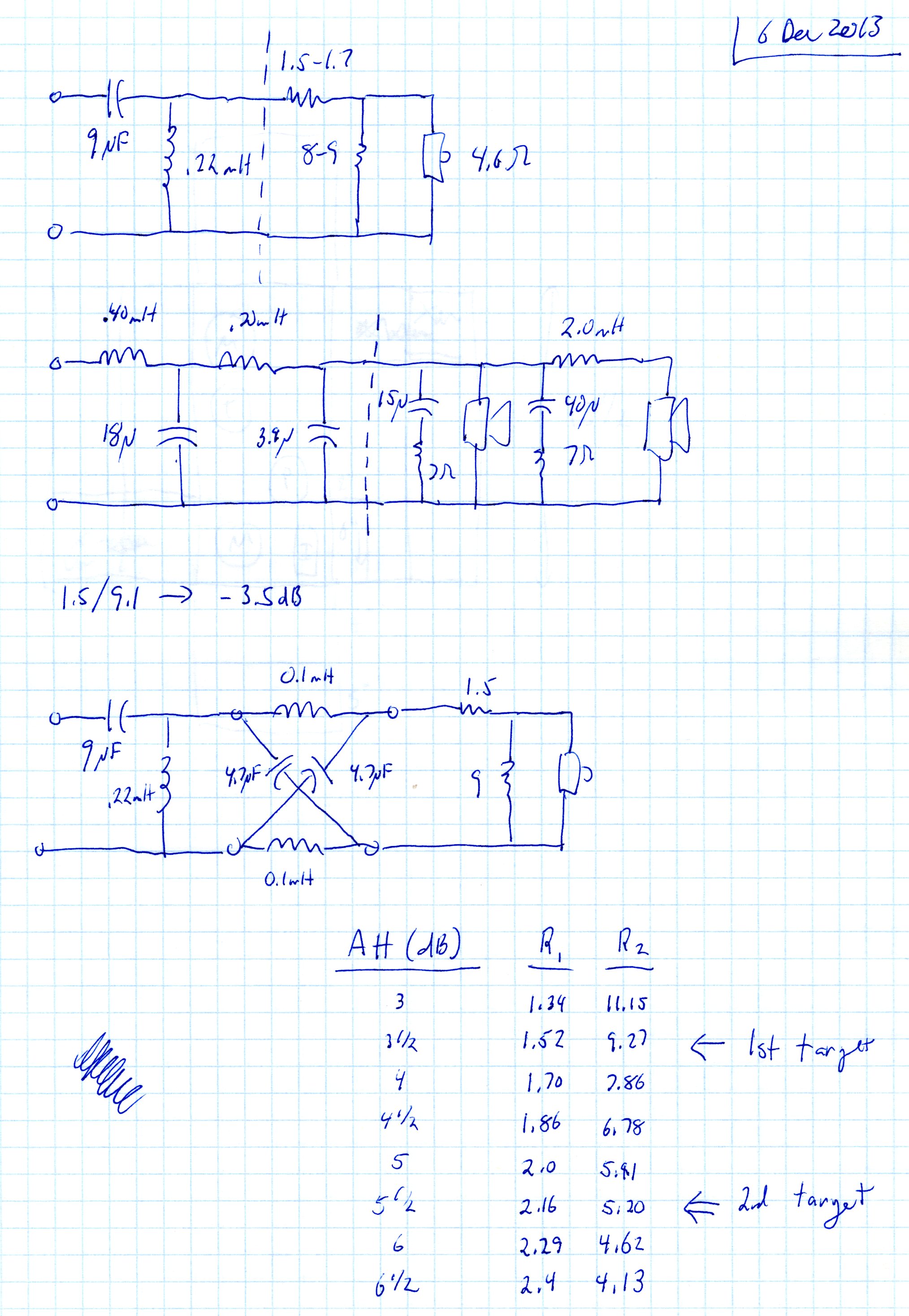
The next crossover design. The target for this crossover is a 4th order LR at 2.5 kHz. The tweeter circuit is electrically 2nd order at 3.6 kHz which combines with the natural 2nd order low-frequency roll-off of the tweeter at 1.0 kHz. Two tweeter circuits are shown… the top is a basic 2nd order with attenuator. The bottom circuit also includes a phase shift circuit. The mid-range circuit is truly 4th order electrical, although it is not a electrically LR.
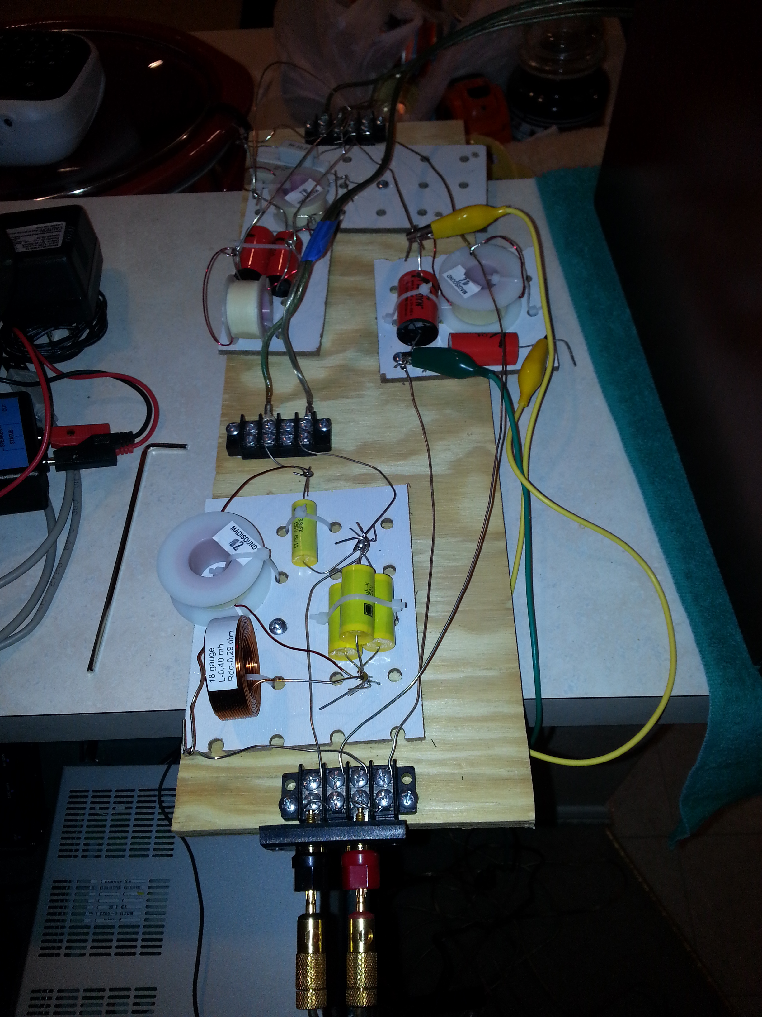
Here is the crossover prototype boards. Sub-circuits are on separate boards so inductors can be separated in the cabinet – tweeter crossover, tweeter delay and attenuation, and midrange crossover. The alligator clip jumper wires will be explained below…

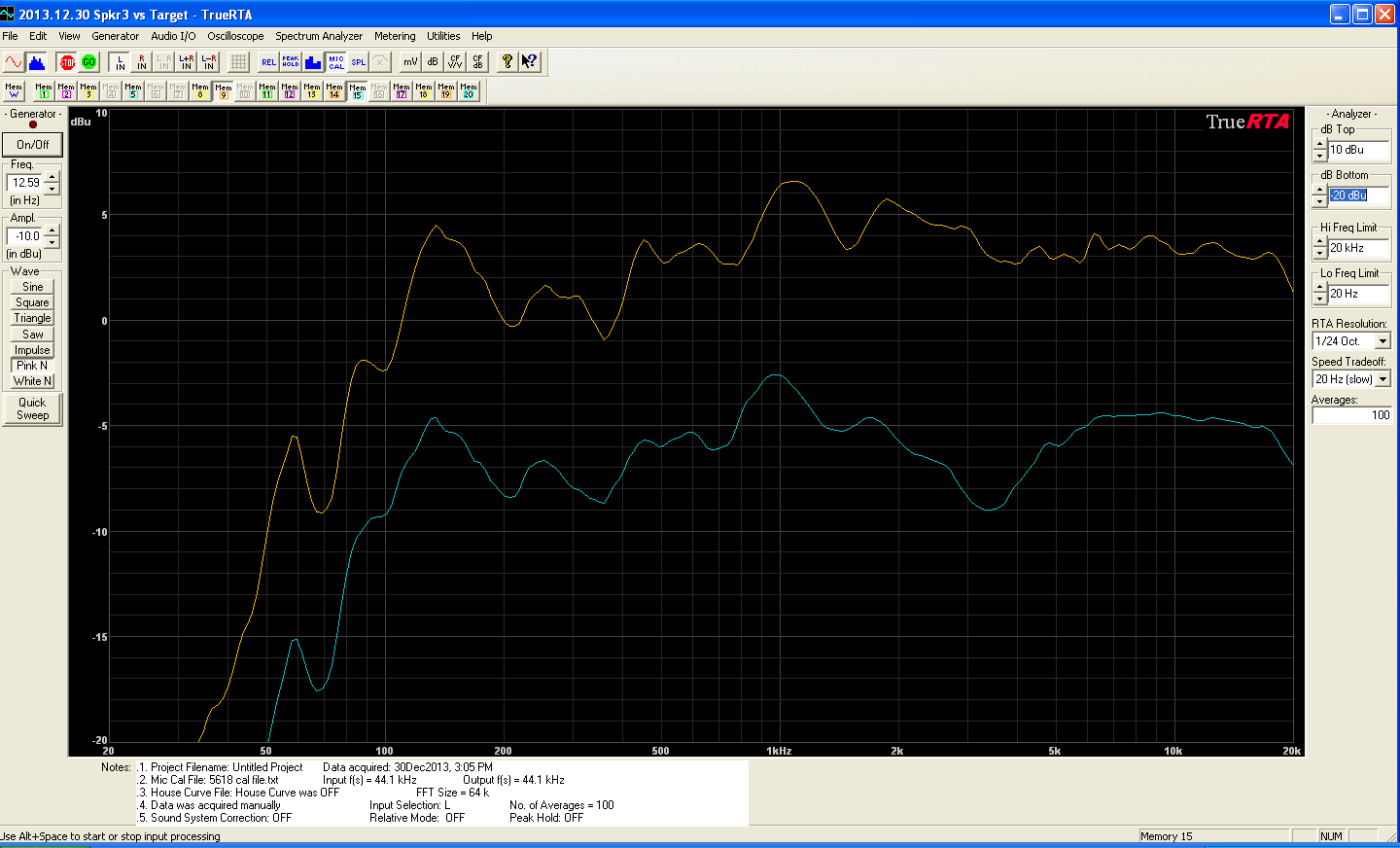
Testing determined two necessary adjustments. First, the tweeter was “hot” by about +2 dB. The attenuator resistors were immediately adjusted from -3.5 dB to -5.5 dB of tweeter attenuation. Second, a suck-out at 3-4 kHz can be seen in the response graph below (lower trace). The suck-out was verified to NOT be a polarity issue. An appropriate deep dip was observed at 2.5 kHz when the tweeter polarity was reversed.
The dip was mitigated by increasing the tweeter output in the 3 kHz region by lowering the crossover frequency and increasing the filter Q. Adding a 4.7 uF in series (via the jumper wires shown above) for a total of 13.7 uF did the trick (upper curve). Note the curves are measured under identical test conditions – a 10 dB offset is added for ease of visualization.
These results emphasize the importance of having some type of acoustic measurement capability when designing loudspeakers!

