Speaker III – Testing with a Bi-Amp

Driver’s mounted – check.  Cabinet port cut – check.  Cross-over – parts on order.

So I drug out some Dayton Audio bi-amplifiers.  What is a bi-amplifier?  Two amplifiers, one each for the tweeter and woofer, along with an electronic cross-over circuit.

Dayton Audio Bi-amp Controls

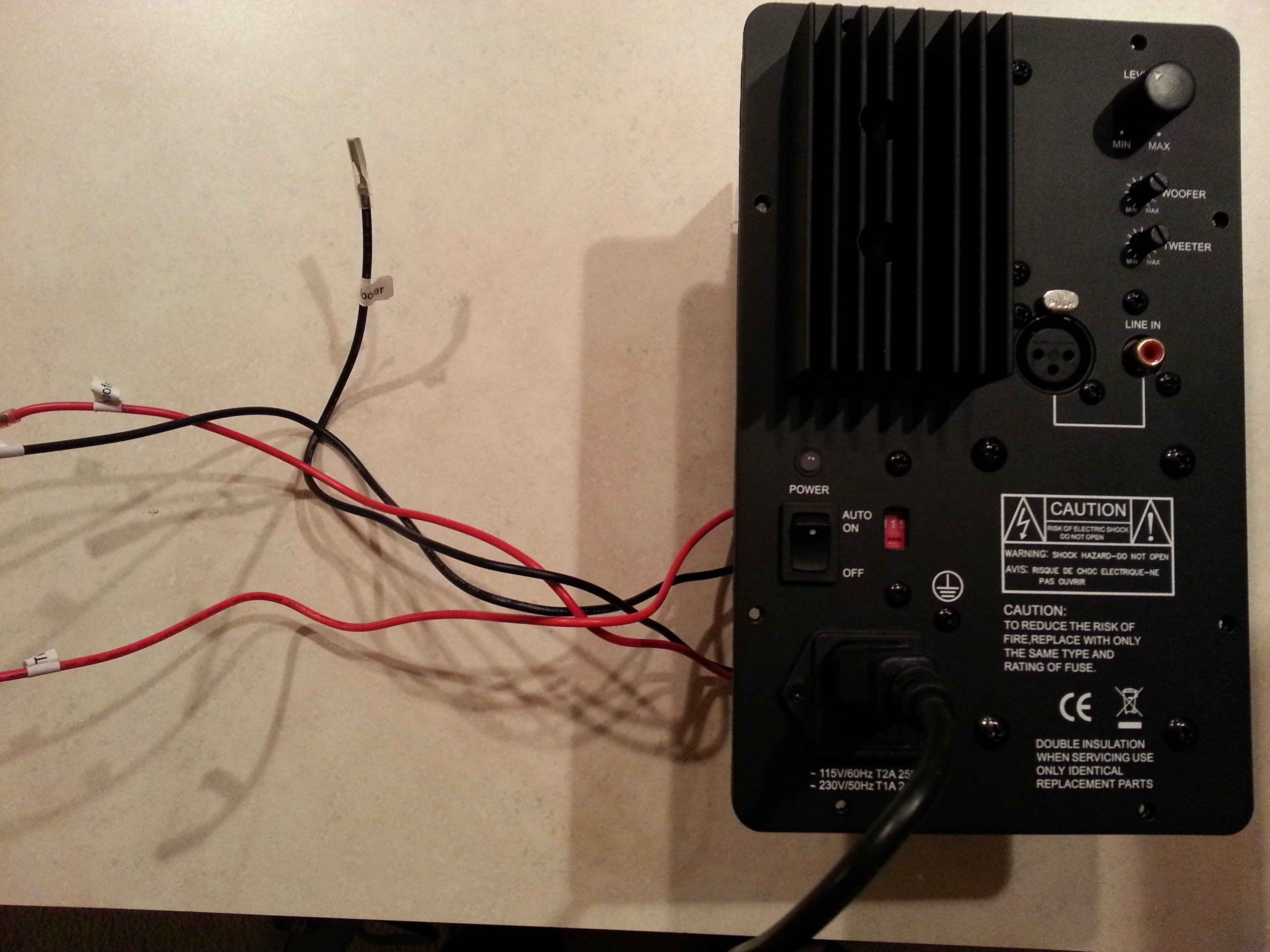
These were the second series Dayton Audio produced.  The high- and low-pass sections have separately adjustable cross-over points.  Frequencies are limited to 2.2 kHz, 3.2 kHz, 3.8 kHz, 4.2 kHz, and 5 kHz.  Order is 4th Linkwitz-Riley.  (In the first series, the cross-over was fixed to 3.0 kHz.)  The electronic crossover also has a +4 dB bass lift circuit.  Presumably the bass-lift is for bass extension.  Looking at the lift cut-out frequency, the circuit actually has the appearance of a diffraction compensation.

Dayton Audio Bi-amp X-over Board

Results – sounded OK with the lift compensation enabled.  Woofers are crossed over at 2.2 kHz, the tweeter at 3.2 kHz.  Just sounded a little bright, maybe 3 dB to hot on the tweeters.

Speaker III – Prototype #4 Rises Again

After 3 years I finally found some time to work on Speaker III.  Getting back to the cabinets, what they need are holes for the port tube and egg crate acoustic treatment.  A couple of bare spots, one each on the top and bottom, are for the crossover boards.  One board for the low-pass, the other for the high-pass, to separate the inductors as much as possible.

Speaker III – Crossover Design #2

img008

The next crossover design. The target for this crossover is a 4th order LR at 2.5 kHz. The tweeter circuit is electrically 2nd order at 3.6 kHz which combines with the natural 2nd order low-frequency roll-off of the tweeter at 1.0 kHz. Two tweeter circuits are shown… the top is a basic 2nd order with attenuator. The bottom circuit also includes a phase shift circuit. The mid-range circuit is truly 4th order electrical, although it is not a electrically LR.

Here is the crossover prototype boards. Sub-circuits are on separate boards so inductors can be separated in the cabinet – tweeter crossover, tweeter delay and attenuation, and midrange crossover.  The alligator clip jumper wires will be explained below…
2014-01-18 17.56.34

Testing determined two necessary adjustments. First, the tweeter was “hot” by about +2 dB.  The attenuator resistors were immediately adjusted from -3.5 dB to -5.5 dB of tweeter attenuation.  Second, a suck-out at 3-4 kHz can be seen in the response graph below (lower trace).  The suck-out was verified to NOT be a polarity issue.  An appropriate deep dip was observed at 2.5 kHz when the tweeter polarity was reversed.

The dip was mitigated by increasing the tweeter output in the 3 kHz region by lowering the crossover frequency and increasing the filter Q.  Adding a 4.7 uF in series (via the jumper wires shown above) for a total of 13.7 uF did the trick (upper curve).  Note the curves are measured under identical test conditions – a 10 dB offset is added for ease of visualization.

2013.12.30 4.7 uF

These results emphasize the importance of having some type of acoustic measurement capability when designing loudspeakers!